

 한국어
한국어 中文简体
中文简体 日本語
日本語 Español
 русский
About us
Our team is proud to offer on time guarantee and product guarantee to customer satisfaction.
Read MoreContact info
- No. 666, Jingtong Road, Danxi Second Industrial Zone, Danxi Town, Yueqing City, Zhejiang, China
- 1696258355@qq.com
- (+86) 15217722885
- 1540939529@qq.com
- (+86) 17857205859
- (+86) 755-83268071
Through Hole Tactile Switch: PCB Mounting and Design Considerations
A Through Hole Tactile Switch is designed to be installed through prepared holes in a printed circuit board. Its terminals extend through the board and are soldered on the opposite side, creating both an electrical connection and a mechanical attachment.
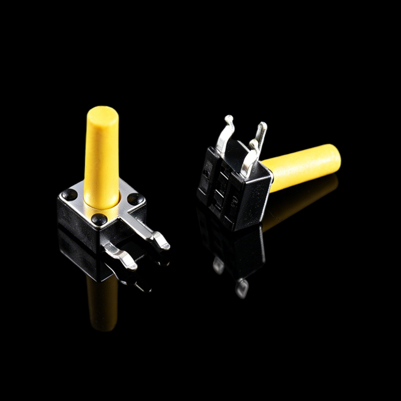
This mounting structure can be useful when a switch needs a stable connection with the PCB. During product development, engineers need to consider the relationship between the switch body, terminals, PCB thickness, and surrounding components.
Pin layout is an important design factor. The terminal arrangement must correspond with the PCB hole pattern. Before producing a board, engineers can review the manufacturer's mechanical drawing and recommended mounting information to ensure that the holes are positioned correctly.
Terminal spacing also needs attention. Incorrect spacing can prevent the component from fitting into the PCB or create unnecessary mechanical stress during assembly.
The physical body of the switch should also have enough clearance from nearby components. Components positioned too close to the tactile switch may interfere with actuator movement or create difficulties during soldering and inspection.
Mechanical support is another reason to consider the mounting structure during design. A through hole switch is physically connected to the board through its terminals, so the PCB and switch should be considered as part of the same assembly system.
PCB Layout and Assembly
PCB layout preparation should take the complete switch structure into account. Engineers need to consider the footprint, hole arrangement, actuator position, body dimensions, and surrounding clearance when placing the component.
The actuator should remain accessible after the PCB is installed inside the enclosure. Its position should correspond with the external button or panel opening. If the actuator is positioned incorrectly, the finished product may have an uncomfortable or unreliable pressing action.
Clearance around the actuator is also important. The button needs enough space to move without contacting the enclosure or nearby components. This becomes particularly relevant when the switch is installed below a control panel or decorative button cap.
Soldering conditions should also be considered during assembly planning. The selected switch should be suitable for the intended soldering process and PCB material. Assembly teams can review the component specifications and process requirements before production.
Manual assembly and automated assembly may involve different handling considerations. A component designed for through hole mounting can be inserted into the PCB and soldered as part of the board assembly process. The production method should be compatible with the switch structure and terminal design.
Inspection after soldering can help identify issues such as incomplete joints, incorrect positioning, or mechanical damage. The switch should also be tested for normal actuation after assembly.
Design Factors Before Production
The relationship between the PCB and product housing should be reviewed before the design is finalized. A tactile switch is not an isolated component because its actuator must interact with the external button or panel.
Housing dimensions can determine the suitable actuator height. Engineers should measure the distance between the PCB surface and the point where the external button contacts the switch.
Button caps are another consideration. Different caps may require different actuator shapes, heights, or contact positions. Compatibility should be confirmed through technical drawings or physical samples.
Actuation direction also matters. The force applied to the switch should generally correspond with the intended pressing direction. Side forces or uneven loading can affect mechanical behavior and should be considered during enclosure design.
Sample testing provides an opportunity to evaluate the actual assembly. Engineers can install the switch on a prototype PCB, place it inside the enclosure, and check button movement, tactile feedback, clearance, solder joints, and overall fit.
For purchasing teams, it is useful to provide suppliers with PCB drawings, housing requirements, actuator specifications, and application information when requesting a component. Clear technical communication can reduce changes during the development process and make it easier to identify a suitable Through Hole Tactile Switch.

©️ 2026 Wenzhou Hanjing Electronics Co., Ltd.

Waterproof Switch Manufacturer
